What does the red band mean?
Dual sync cords have a primary and secondary side so only one ready light signal is sent to the camera. The secondary cord which does not have a ready light signal is marked with a red band. This is the strobe that should be turned off if only one strobe is to be used. This is easy to remember because logic dictates red would be the primary side, but Ikelite got it backwards and put it on the secondary side.
What does the blue band mean?
The blue band designates it as a "digital" sync cord. For Ikelite-to-Ikelite sync cords, this means that all 5 conductors are wired. For Ikelite-to-Nikonos sync cords, this means that only 2 conductors are wired (trigger and ground).
Can I use non-Ikelite lubricant?
Some non-Ikelite brands of lubricants have been known to cause softening and swelling of our o-rings. We recommend using only Ikelite silicone lubricant on all of our o-rings to prevent potential problems or flooding.
Are the cord connector caps waterproof?
No. The caps including with our sync cords are intended to be dust caps for storage only. The caps fit loosely on the ends to prevent the o-rings from taking a set over long periods of time. There is not enough pressure exerted on the o-ring to keep the end watertight at depth. Diving with a dust cap on your sync cord will result in a damaged cord.
What if my housing has two bulkheads?
Housings that have two Nikonos style bulkheads are not always wired correctly to utilize dual strobes with one strobe attached to each bulkhead. Dual strobes (one connected to each bulkhead) may not operate correctly if both bulkheads connect all five conductors to the camera. Five conductors from each bulkhead would allow either strobe to operate TTL, but not both simultaneously. One should have five conductors and the other connect only three conductors for dual strobe operation.
We have seen Aquatica, Seacam, Nexus, and Subal housings with two Nikonos style bulkheads wired with all five conductors connected to the camera, requiring a dual cord attached to just one bulkhead. The manufacturer should be able to tell you if their wiring is compatible with accepted protocol.
Wiring Diagrams + Test Firing Strobes
Use the appropriate diagram below to help in testing and analysis of Ikelite sync cords and strobes. If a sync cord is attached to the strobe, for example, the diagram indicates which pins on the other end of the cord can be connected with a paper clip to test the strobe functions. If continuity of a cord is being tested, the diagrams indicate the matching connector on the other end of the cord. You can use a multimeter to test continuity.
Please pay attention and exercise extreme caution when using these wiring diagrams to test fire your strobe. Shorting across the incorrect connectors can cause damage to your strobe. Equipment may be returned to us at any time without prior authorization for testing and repairs as necessary.
Ikelite TTL Bulkhead
Look at the Ikelite bulkhead as installed on strobes and housings, with pins on the bottom as shown at right. Connecting GROUND to TRIGGER should fire the strobe.

If attempting to install an Ikelite bulkhead, we use the following color conventions:
- Red wire READY light
- Green wire QUENCH
- Black wire GROUND
- White wire TRIGGER
- Power for TTL Circuitry
The colors listed above are provided only for reference in the assembly of an Ikelite bulkhead. Wire colors are not visible in fully assembled bulkheads as found in products. Power for TTL circuits does not apply to older, non-digital TTL bulkheads.
If a sync cord is attached to the strobe, for example, the diagram indicates which pins on the other end of the cord can be connected with a paper clip to test the strobe functions. If continuity of a cord is being tested, the diagrams indicate the matching connector on the other end of the cord. You can use a multimeter to test continuity.
Please pay attention and exercise extreme caution when using these wiring diagrams to test fire your strobe. Shorting across the incorrect connectors can cause damage to your strobe. Equipment may be returned to us at any time without prior authorization for testing and repairs as necessary.
Ikelite TTL Sync Cord
Look at the Ikelite sync cord plug connector which attaches to DS strobes and TTL housings, with pins on the top as shown at right. Connecting GROUND to TRIGGER should fire the strobe.

If attempting to install an Ikelite plug, we use the following color conventions:
- Red wire READY light
- Green wire QUENCH
- Black wire GROUND
- White wire TRIGGER
- Power for TTL Circuitry
Non-digital (non-DS) strobes will blink the ready light when GROUND and QUENCH are connected.
The colors listed above are provided only for reference in the assembly of an Ikelite bulkhead. Wire colors are not visible in fully assembled bulkheads as found in products.
If a sync cord is attached to the strobe, for example, the diagram indicates which pins on the other end of the cord can be connected with a paper clip to test the strobe functions. If continuity of a cord is being tested, the diagrams indicate the matching connector on the other end of the cord. You can use a multimeter to test continuity.
Please pay attention and exercise extreme caution when using these wiring diagrams to test fire your strobe. Shorting across the incorrect connectors can cause damage to your strobe. Equipment may be returned to us at any time without prior authorization for testing and repairs as necessary.
Nikonos N5 Sync Cord
The wiring diagram shows a newer plug with 5 receptacles. This wiring is the same as older cords with three receptacles (in GROUND, TRIGGER AND READY positions) and two pins (in 3.3K OHM AND QUENCH positions). Look at the Nikonos sync cord plug connector, with the index groove on the bottom as shown at right. Connecting GROUND to TRIGGER should fire the strobe.
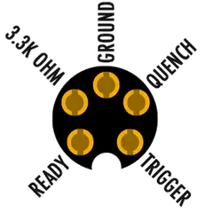
A 3.3K ohm resistor is installed inside of the plug, connecting the ground circuit to the pin identified as 3.3K ohm. This internal connection indicates to the camera that a TTL strobe is attached, and it provides proper operation with any brand of housing that has a Nikonos N5 bulkhead.
If a sync cord is attached to the strobe, for example, the diagram indicates which pins on the other end of the cord can be connected with a paper clip to test the strobe functions. If continuity of a cord is being tested, the diagrams indicate the matching connector on the other end of the cord. You can use a multimeter to test continuity.
Please pay attention and exercise extreme caution when using these wiring diagrams to test fire your strobe. Shorting across the incorrect connectors can cause damage to your strobe. Equipment may be returned to us at any time without prior authorization for testing and repairs as necessary.
Nikonos N5 Bulkhead
This diagram may be used to test continuity with a Nikon TTL hot shoe. For manual strobe operation, only GROUND and TRIGGER need to be wired.
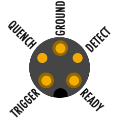
For TTL strobe operation, all five conductors need to be wired properly.
Check with your housing manufacturer for the most accurate information on how their bulkhead and hotshoe are wired. Incorrect wiring will prevent strobes from operating properly or providing TTL operation (using a compatible TTL converter).
Over the years various housing manufacturers have introduced a variety of Nikonos-style bulkheads with variations on the original contact design. Traditionally the QUENCH and DETECT pins will be spring loaded.
Nikon TTL Hot Shoe
Look at the Ikelite sync cord plug connector which attaches to DS strobes and TTL housings, with pins on the top as shown at right. Connecting C (ground) to D (trigger) should fire the strobe.
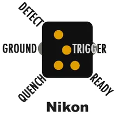
- Ikelite white wire TRIGGER = Nikon white wire
- Ikelite black wire GROUND = Nikon black wire
- Ikelite red wire READY light = Nikon blue wire
- Ikelite green wire QUENCH = Nikon red wire
- Ikelite 10K ohm resistor DETECT = Nikon yellow wire
The colors listed above are provided only for reference in the assembly of an Ikelite bulkhead. Wire colors are not visible in fully assembled bulkheads as found in products.\
Originally published at www.ikelite.com